Signal Transformers#
The transformers for the sensing stage are handmade.
What we can act on is the number of turns, which has effect on:
transformation ratio
magnetizing impedance
In brief we need:
a certain transformation ratio to have an acceptable level for the ADC at the output;
a certain transformation ratio so that the downstream (i.e. resistors) has minimal influence on the upstream
high/low enough magnetizing impedance (high for voltage sensor and low for current sensor);
See here for the model of a transformer.
Design#
The design procedure is done following some basic rules that can be found in Fundamentals of Power Electronics [Erickson and Maksimović, 2020] Part III.
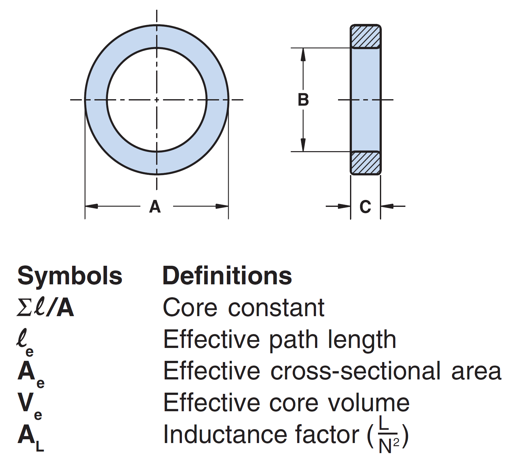
Fig. 7 Main dimension in a toroidal core#
The reluctance of the core is given by
where \(l_e\) is the length of the magnetic path (i.e. average-circumference) and \(A_e\) the area of the cross-section perpendicular to the magnetic path. The magnetizing inductance is
where \(N\) is the number of turn of the side where we are interested to model the inductance. In brief:
The value of permeability in vacuum is \(\mu_0=1.256\times 10^{-6}\;\frac{N}{A^2}\), equivalently \(\mu_0=4\pi\times 10^{-7} \frac{H}{m} = 4\pi\times 10^{-4} \frac{H}{mm}\).
insert an interactive interface https://ipywidgets.readthedocs.io/en/latest/examples/Widget List.html
With the transformer we are in phase-advance
Built transformers with data#
Measure are obtained with the RLC measurement machine in GAEI Lab.
Available core#
The core that are available for transformers are:
<table with the cores>
core code |
|
|---|---|
77206A7 (grey core big) |
|
5977000301 (black core small) |
|
5978002701 (black core medium) |
|
B64290L0618X038 (blue core - CT) |