Resonant Tank#
The core of the resonant tank is composed by an inductor \(L_r\), a capacitor \(C_r\) and a transformer \(T_r\) (with magnetizing inductance \(L_m\)). The input is a square waveform generated by an H-bridge and the output of the transformer is a sinusoidal waveform.
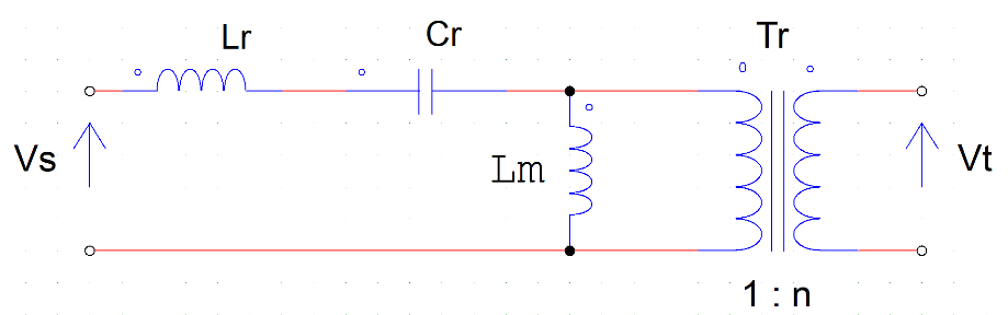
Fig. 4 Resonant tank#
Maximum rating on the components for an output battery current of 10A
Maximum inductor current: 35A AC (high Q) - 15A AC (low Q)
Maximum capacitor voltage: 900V AC (high Q) - 50V AC (low Q)
The first winding of the current transformer has to withstand the full current, need proper size of the wire.
Resonant Elements#
The main resonance frequency is defined as \(f_r=\frac{1}{\sqrt{L_rC_r}}\). The transformer has a transformation ratio of \(n\).
Inductor \(L_r\)#
The inductor should be an AC inductor. The design procedure differs from “standard” inductors that are used in converters, which are DC. In AC inductors we need to pay attention to the core losses (?), which are usually neglected for AC.
Important
Nevertheless, we choose inductors from the Coilcaft in the series AGP since, even if for DC, they showed good properties for a proof-of-concept prototype in which we are relatively interested in the efficiency.
And in indeed with high-current it is overheating.
Capacitor \(C_r\)#
For the choice of the capacitors we need to consider that the voltage and the current that might be really high resulting in rising temperature.
For the voltage. there are different ratings, while for the current we need to look at the thermal coefficient.
In brief, the best ones to this scope are the ceramic capacitors with temperature coefficient C0G with SMD package. They have the lowest value =0 with lowest tolerance and the capacitance value is almost insensitive to variations in the temperature.
Usual SMD capacitors that are used are the X7R but with high current they tend to overheat.
Tip
Use C0G or NP0 smd capacitors.
Warning
We used X7R capacitors for the low quality factor resonant tank, and they result in easily overheat.
Transformer \(L_m\)#
The transformer are hand-winded using Litz wire. The main objectives are:
isolate the downstream of the circuit, i.e. source and load;
adapt voltage level if needed;
introduce a magnetizing inductance that made the resonant tank of the 3rd order (better frequency response for the scope).
There is an excel file with the design of the transformers.