Rectifier#
At the power level objective is to rectify the AC output of the transformer and filter it so that the ripple is at an acceptable level for the battery.
The main parts of the board are:
power part with:
rectifier
3rd filter low-pass filter
battery connection
sensing part with:
voltage sensor
current sensor
ADCs.
At high level, the main objective is to control the current charging the battery while ensuring galvanic isolation between the battery and the FPGA (ideally, the FPGA should be isolated from both battery and H-bridge).
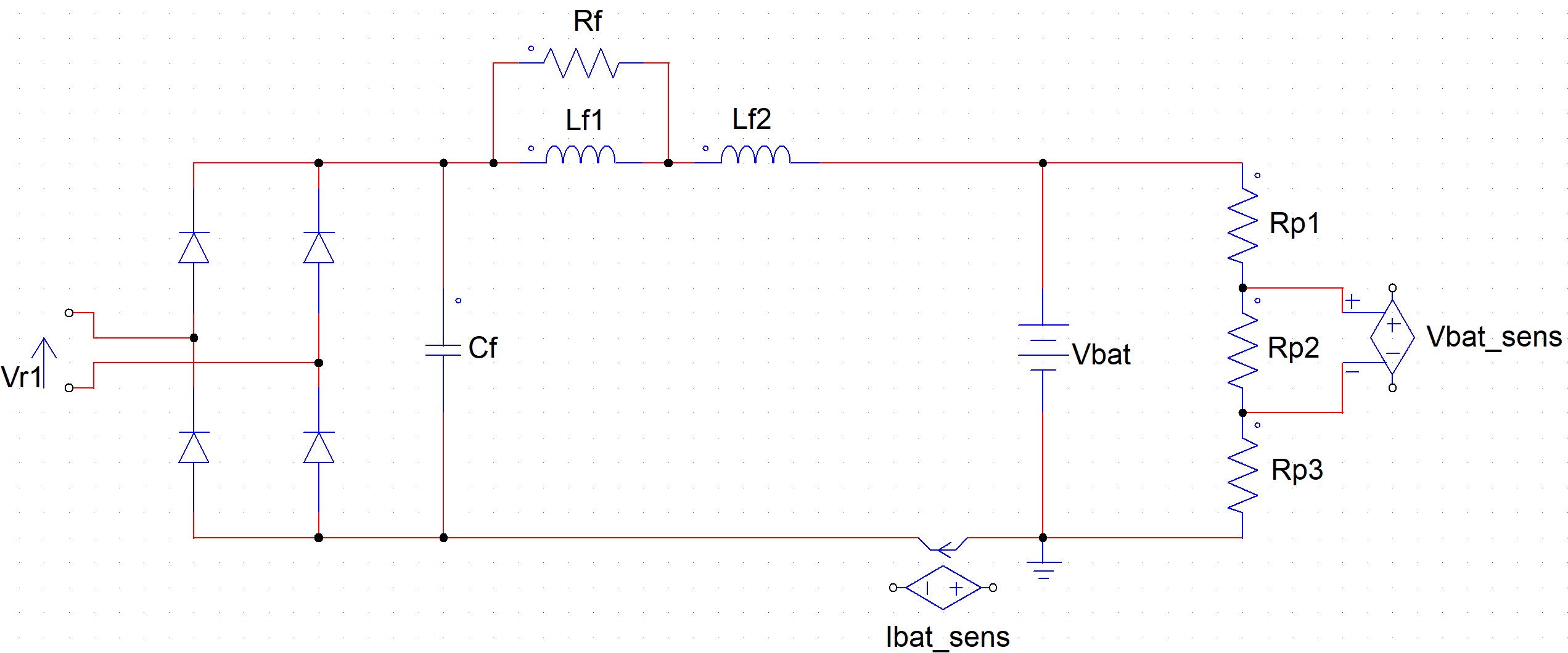
Fig. 8 Overview of the main power parts#
Diode Bridge#
The diodes used for the bridge should have a fast recovery. To this end, Schottky diodes are suggested. Moreover, the two parameters important for the design/choice are: the current flowing through them, and the maximum reverse voltage.
On the other side, parameters that are influencing the behavior are the threshold voltage and recovery time.
The bridge output current is a pulsating wave \(i_{r}(t) = I_{r}\left| \sin\left( \text{ωt} \right) \right|\). The average DC value is \(\frac{2}{\pi}I_{r}\).
Diodes are subject to 50% of \(i_{r}(t)\). The diodes need a heat-sink in
order to dissipate the heat. The ‘head’ is connected to the cathode and
must be isolated from the others (silicone + mica).
Average forward current is equal to \(\frac{I_{r}}{\pi}\).
Two possible choices for the diodes from Vishay are:
\(\mathbf{I_F}\) |
\(\mathbf{V_R}\) |
\(\mathbf{V_F}\) |
|
|---|---|---|---|
VS-15TQ060-M3 |
15A |
60V |
0.56V |
FES16BT-E3/45 |
16A |
100V |
0.975V |
Filter#
Maybe add some consideration on the harmonic decomposition: MATLAB FFT analysis? Useful to understand the behavior of the filter.
The filter is composed of one capacitor, two inductors and a resistor. The input is a pulsating wave and the filter has the objective to smooth the oscillation (reduce the ripple).
We can write the following relation between input and output current in the frequency domain:
The transfer functions are
with DC gains \(H_{i}(0) = 1\) and \(H_{v}(0) = 0\). Therefore, since we can consider the battery voltage almost constant, it has no influence on the filtered current that fully depends on the rectified current. The DC part is kept, and we have cut-off frequency at: need numerical solution!
Note
Can put a widget to calculate the cut-off frequencies of the filter. A 3rd order equation need to be solved
TO CHECK: Lower cut-off frequency (2nd order pole) depends mostly on the reactive components and not on \(R_{f}\). \(R_{f}\) has an stronger influence on the higher cut-off frequency (1st order pole).
Choice of the inductors \(\mathbf{L}_{\mathbf{f}\mathbf{1}}\) and \(\mathbf{L}_{\mathbf{f}\mathbf{2}}\)#
We need inductors in the range 1uH-3uH. Würth Elektronik offers some compact solutions; another solution is to use classical toroidal one like the ones from Bourns
code |
L |
\(I_{R}\) |
\(I_{\text{sat}}\) |
\(R_{\text{DC}}\) |
||
|---|---|---|---|---|---|---|
WE-HCFT |
7443762504010 |
1uH |
39A |
33A |
0.86m |
|
7443762504022 |
2.2uH |
30A |
23.8A |
1.78m |
||
BOURNS |
2100LL-1R0-V-RC |
1uH |
21.4A |
2m |
|
|
2100LL-1R5-V-RC |
1.5uH |
18.5A |
3m |
|||
actual selection |

At the end, we opted for the Wurth inductors.